 Knowledge Base
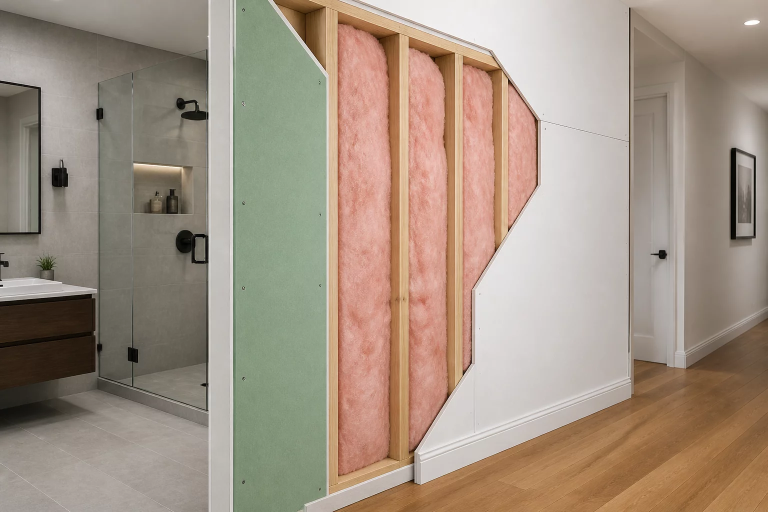
How One Wall Belongs to Two Distinct Scope Questions
Deconstructing interior partition assemblies where opposing faces encounter divergent environmental exposures and separate scope obligations.
Eliminating desk review disputes through visible geometric boundaries, threshold dividers, and verifiable floor plan coordinates.
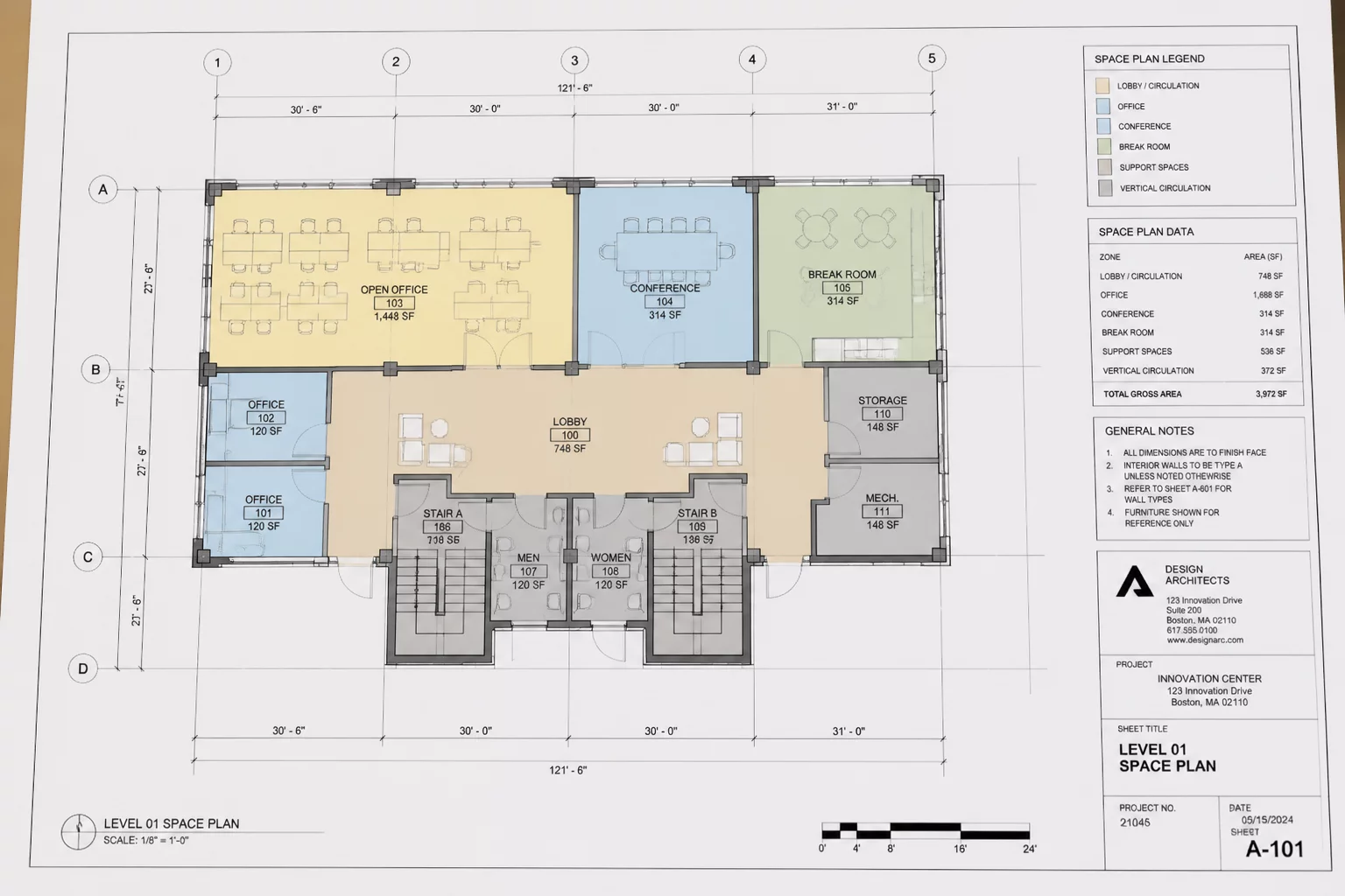
External claim examiners and independent audit teams evaluate hundreds of scoping packages weekly. When confronted with nested rows of drywall removal, subfloor substrate prep, or specialized containment barriers, desk reviewers default to skepticism whenever lineal footage totals fail to align intuitively with generic architectural perimeters. An isolated tabular list provides zero contextual geometry. The reviewer cannot ascertain whether an eighty-square-foot insulation charge belongs to an exterior perimeter wall, an offset plumbing chase, or a shared common corridor partition.
Plan-view graphic demarcation addresses this structural disconnect directly. Rather than forcing the auditor to mentally reconstruct three-dimensional framing relationships from raw numbers, a demarcated 2D architectural plan overlays color-coded perimeter bounds, designated doorway break lines, and numbered zone markers. Every item in the tabular line estimate corresponds to a clearly outlined polygon on the plan. This immediate clarity prevents auditors from slicing legitimate surface repairs under the assumption of redundant overlap.
Constructing a defensible plan-view overlay begins with isolating distinct construction assemblies onto explicit graphic layers. Boundary perimeters must not merely outline structural masonry or exterior studs; they must establish exact stopping lines at cased openings, open-concept transitions, and height breaks. When dealing with open floor layouts where a kitchen flows uninterrupted into a living room, an auditor will routinely contest flooring or ceiling scopes unless an explicit virtual threshold is drawn on the plan with labeled bounding dimensions.
"A quantity calculation divorced from physical floor plan coordinates invites arbitrary audit cuts. Graphic demarcation turns disputed estimates into verifiable spatial facts."
Furthermore, trade demarcation should consistently distinguish vertical assemblies from horizontal planes. Annotating wall faces with distinct stroke weights and hatching patterns enables remote reviewers to distinguish between one-sided surface repairs and through-cavity structural interventions. By embedding indexed matrix numbers directly inside the plan's room boundaries, the documentation file creates an ironclad audit trail that stands up to the most rigorous third-party peer assessments.
Auditors look for clearly annotated room dimension strings, distinct boundary colors indicating repair scope versus unaffected areas, labeled threshold cut lines at doorways, and cross-referenced zone IDs linking directly to estimate line items.
By defining exact polygon bounds with non-overlapping color fills and center-jamb threshold dividers, the plan proves mathematically that no square footage or perimeter linear footage has been counted in two adjacent room scopes.
Yes. Most industry estimating software environments, including Xactimate Sketch, provide tools for adding sub-rooms, missing walls, dimension lines, and custom text callouts that conform to standard audit demarcation practices.
A plan view shows zone boundaries against recognizable room geometry, letting an auditor verify scope without a site visit.
Zone labels, boundary lines at verified physical anchors, and a legend tying each zone to its matrix row.
No - the graphic supports the matrix but the tabular record remains the authoritative quantity source.
Boundaries must match real anchors within normal measurement tolerance; schematic precision matters less than correct physical anchoring.
Knowledge Base
Deconstructing interior partition assemblies where opposing faces encounter divergent environmental exposures and separate scope obligations.
 Knowledge Base
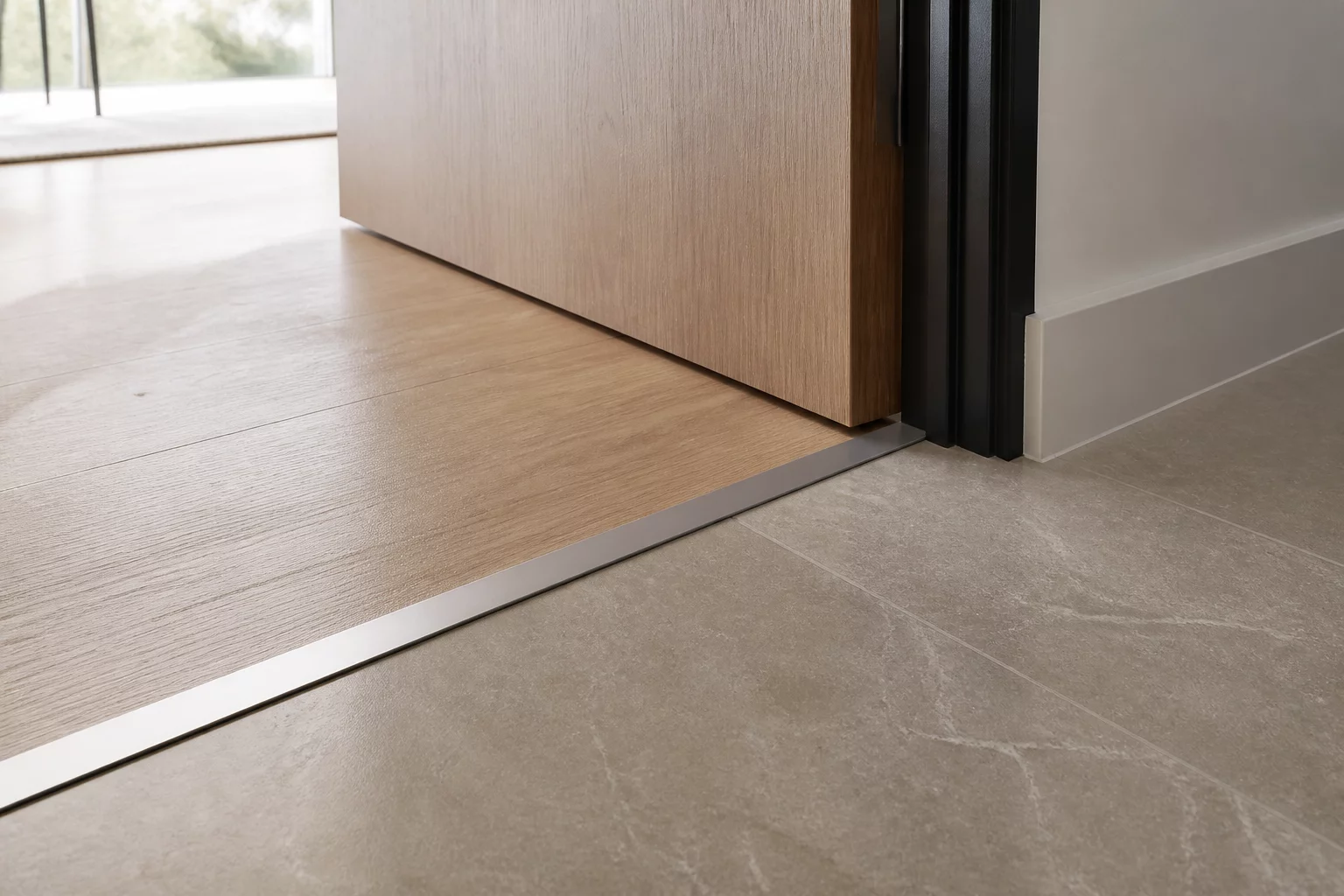
Establishing indisputable room boundaries and flooring transition cuts directly beneath door slabs to prevent audit deductions.
 Knowledge Base
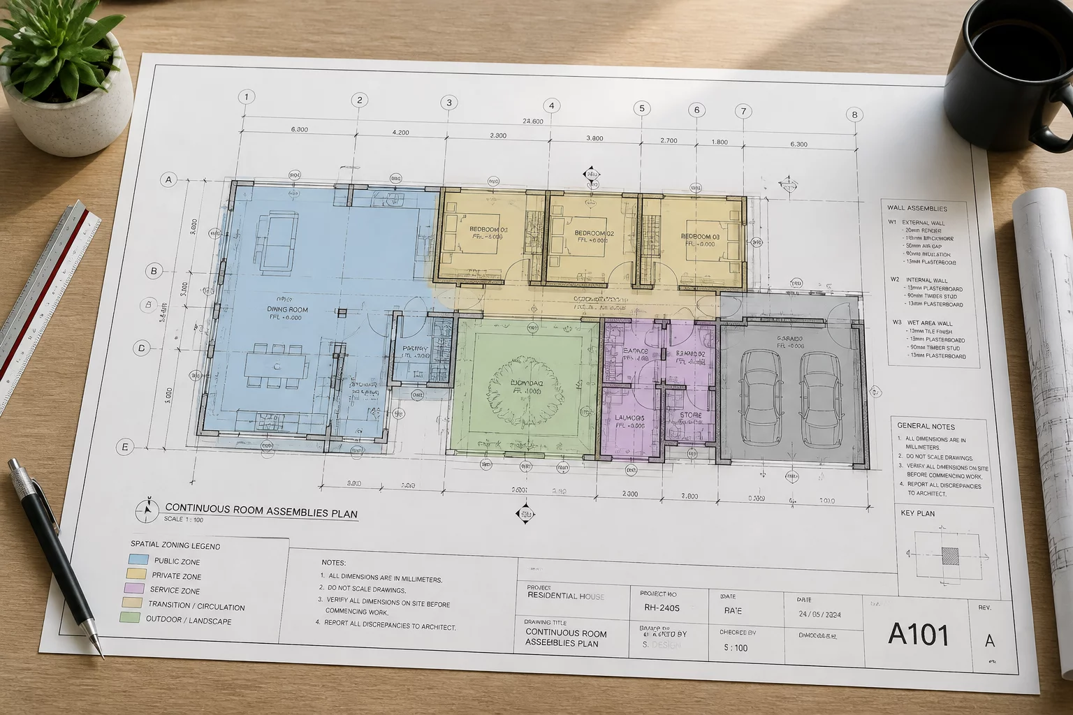
Avoiding the perilous trap of aggregating quantities across contiguous rooms without documented partition boundaries.
Discussion & Observations
No observations yet. Be the first to leave a comment.
Submit Methodology Observation