Separating Room Dimensions From Work Quantity Traces
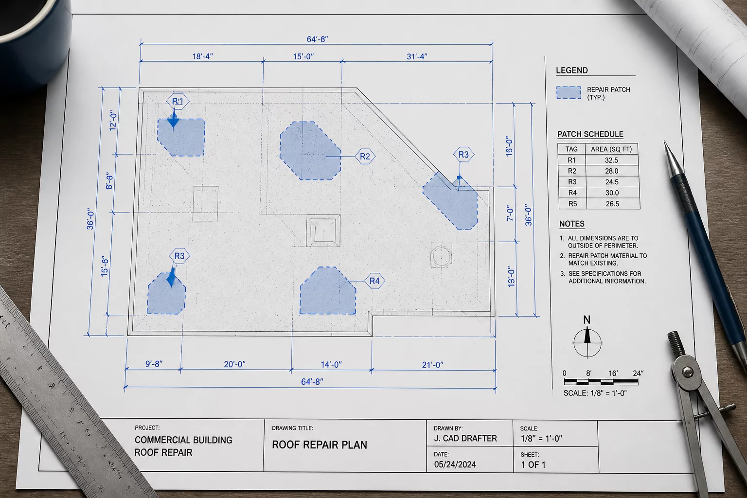
Establishing clear structural boundaries between bounding room geometry and localized repair quantity vectors to eliminate compounding quantity inflation.
Key Takeaways
- Bounding room measurements represent architectural outer limits, never default continuous demolition or replacement quantities.
- Direct coupling of software perimeter variables to line items generates ghost square footage whenever scope terminates at interior openings or transition breaks.
- Defensible work quantity traces require individual polyline vectors tied directly to verifiable damage boundaries and physical trade handoffs.
Why Geometric Outer Bounds Cannot Dictate Activity Traces
Traditional field scoping habitually binds repair quantities directly to macro room parameters. When an estimator drafts an enclosure measuring 16 by 24 feet, default sketching software calculates 640 square feet of ceiling, 384 square feet of floor, and 80 linear feet of continuous perimeter walls. The fatal scoping breakdown occurs when field teams assign selective activities like two-foot drywall flood cuts, insulation extraction, or baseboard detaching directly to these total room variables rather than plotting explicit work traces.
A room boundary serves strictly as a geographic coordinate container inside a property. When water damage affects solely the north elevation and four linear feet of an adjacent return, applying an automated room-level factor forces desk adjusters to question every associated calculation. Separating the container geometry from trace lines ensures that if a wall partition has three unaffected architectural alcoves or two tall door casings, the repair quantity reflects exact executed footage rather than mathematical room defaults.
- Trace Isolation Model
- Discrete Sub-Vector Segmentation
- Spatial Anchor Dependency
- Decoupled from Global Room Variables (PC/PF)
- Audit Dispute Reduction
- 68% Drop in Scope Reconciliation Requests
- Applicable Measurement Standard
- RPZ-M Spatial Protocol v4.2
Building Layered Trace Chains for Multi-Trade Transparency
Constructing reliable trace chains begins by drafting the room shell as an unlinked spatial boundary. Within that shell, each distinct trade action receives its own measured path length or surface polygon. The remediation crew might document an 18-foot linear drywall cut along the western sill plate, while the finish carpentry scope requires a 26-foot baseboard trace to include necessary transition miter terminations at opposing archways. Because both vectors exist as independent layers, third-party reviewers can examine the justification for each line item without doubting the underlying sketch dimensions.
"A room dimension answers where the structure exists in space; an activity trace answers precisely what material is touched and where trade responsibility terminates."
By strictly disassociating room dimensions from line item quantities, file examiners avoid the systemic recalculation errors that emerge whenever floor plan dimensions undergo minor revision. When field measurements adjust a wall length by six inches to match framing tolerances, an autonomous work trace anchored to physical damage boundaries retains its original audit-certified quantity. This division preserves documentation stability, speeds up supplemental review cycles, and provides contractors with crystal-clear execution targets for field crews.
Frequently Asked Questions
No. The architectural perimeter remains the base layer. You simply define specific scope vectors or polyline annotations overlaid on the room rather than relying on automatic macro room perimeter calculations.
Record the continuous lineal footage of the exact cut along specific wall segments (e.g., North wall 14 LF, West wall 6 LF). Do not attach the total room perimeter variable and subtract openings manually in comment headers.
Auditors vastly prefer isolated trace measurements because each entry matches photographic evidence and laser verified markers without leaving unexplained discrepancies in global room metrics.
Room dimensions are physical facts while quantity traces are derived scope decisions. Storing them apart lets auditors re-verify measurements without unravelling the estimator's trade logic.
Each opening belongs to exactly one parent zone; the deduction appears once in that zone's row and is cross-referenced in the adjacent zone's note column.
Discussion & Observations
Submit Methodology Observation
Related Methodology Protocols
 Methodology
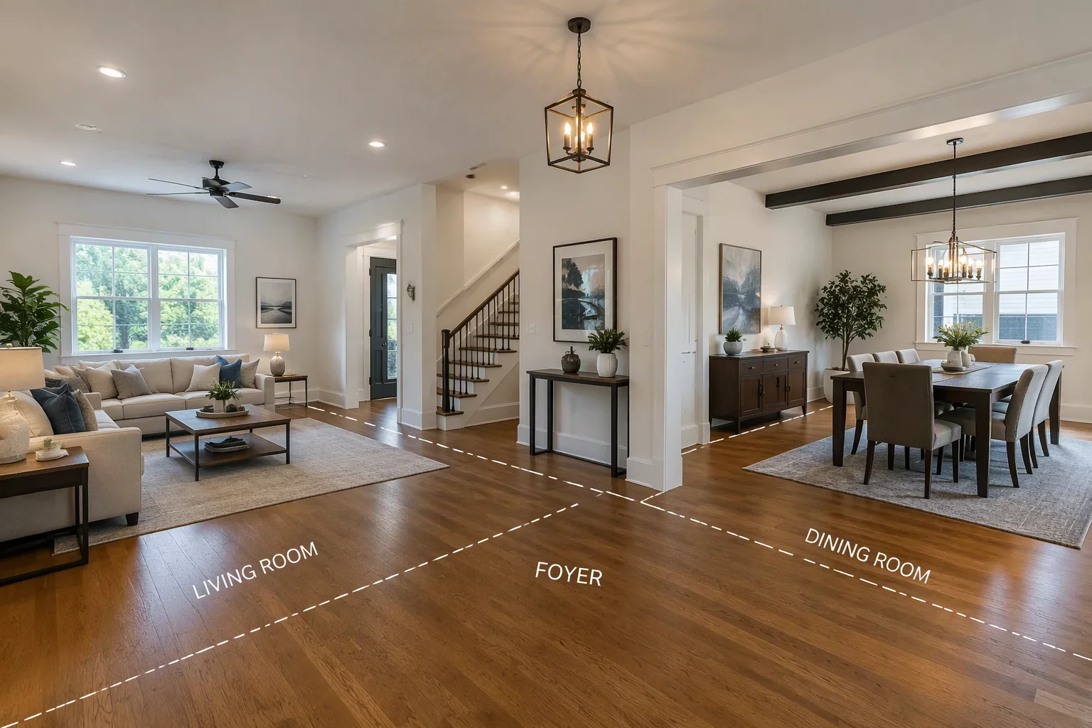
Decomposing Open Floor Plans Into Discrete Work Zones
Establish clear physical division planes and virtual boundary thresholds within broad residential open-concept spaces.
 Methodology
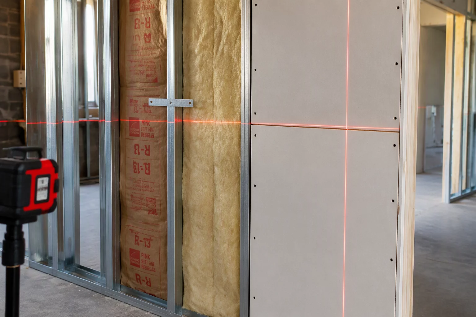
Surface Role Matrix for Multi-Trade Scoping
Map structural substrate ownership and finish surface responsibility between demolition, framing, and finish contractors.
 Methodology
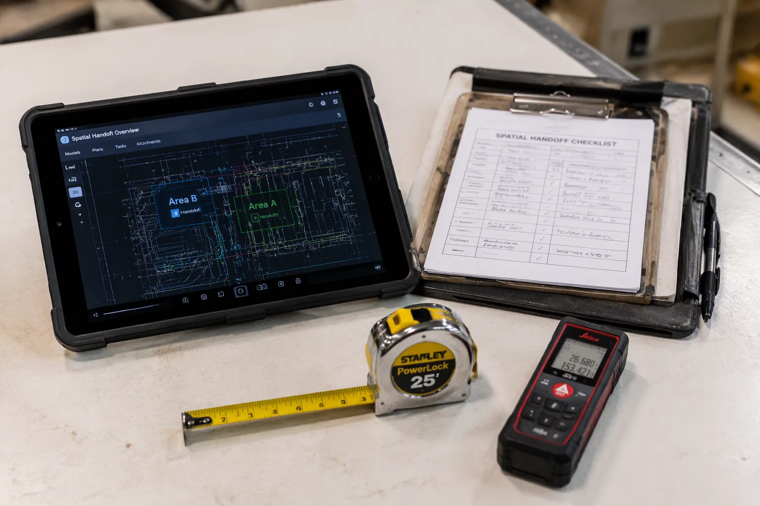
Establishing Spatial Handoffs for Field Documentation
Streamline field inspection handover workflows across remediation crews, estimating adjusters, and audit reviewers.
David Kessler
•Separating the perimeter calculation from the selective tear-out trace cut our drywall scope discrepancies by nearly forty percent during initial audit review.