 Specifications
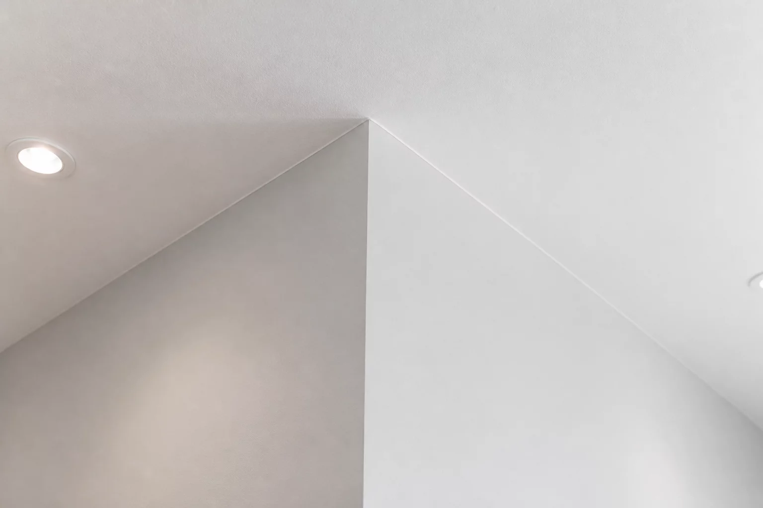
Continuous Drywall & Ceiling Plane Intersections
Scoping transition junctions where partition drywall meets monolithic overhead framing without double-counting corner beads or tape allowances.
Establishing systematic spatial boundaries between suspended T-bar grid components, acoustical tile infill, and overhead structural anchors for clean multi-trade repair line items.
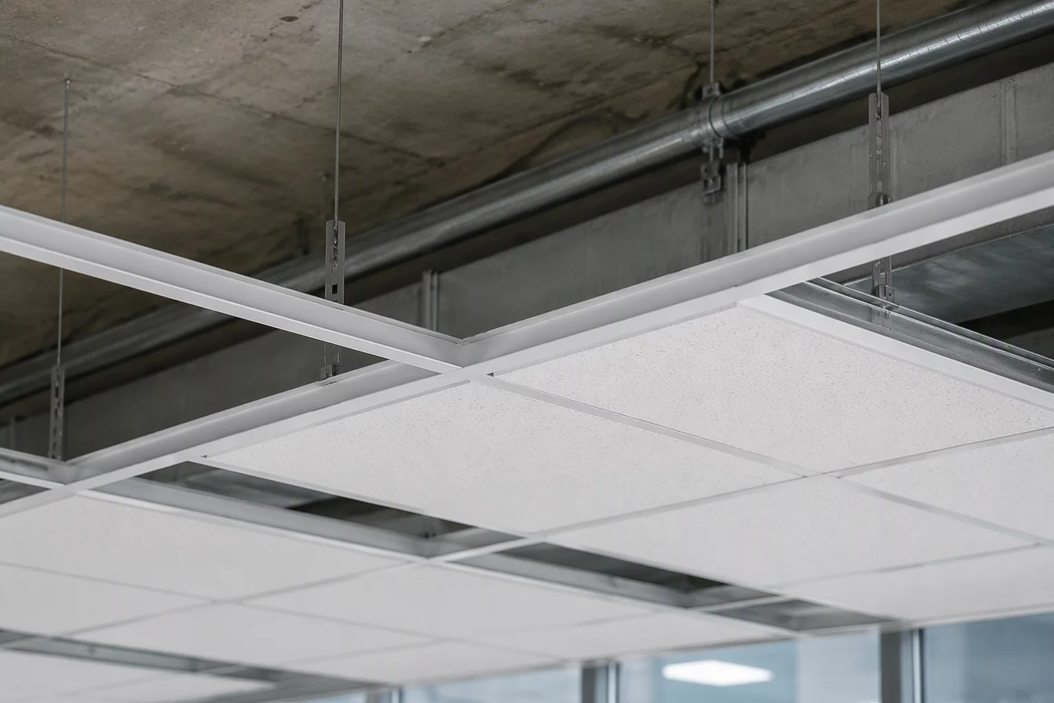
Commercial and institutional interior restorations frequently blur the line between cosmetic acoustical treatment and overhead structural support systems. When moisture intrusions or mechanical failures compromise an acoustic drop ceiling, scoping specialists often lump the entire assembly into a broad surface allowance. This practice leads to severe scope friction during review, as replacing mineral fiber ceiling tiles requires entirely different trade qualifications and labor rates than re-hanging galvanized suspension wire or anchoring seismic struts into precast concrete decks above.
To maintain defensible documentation, our matrix establishes a strict three-tier elevation threshold. Tier 1 governs the primary overhead substrate and anchor points attached to the deck. Tier 2 encompasses the intermediate tension suspension wire, turnbuckles, and lateral seismic bracing. Tier 3 covers the exposed grid network and finished drop-in panels. Isolating these tiers prevents accidental duplication of overhead access equipment while guaranteeing that trade handoffs between structural ironworkers and finishing acoustic installers remain transparent.
When dealing with plenum return airspaces or fire-rated floor-ceiling designs, suspended grids cannot be treated as isolated architectural cosmetic screens. Any wire penetration or unistrut trapeze anchor must preserve continuous membrane integrity. When fire-rated acoustic tiles suffer water saturation, replacing them involves verifying UL assembly design numbers and testing clip attachments on cross tees to resist uplift pressures generated by building HVAC cycling.
“An acoustic ceiling is not merely a single horizontal square-footage quantity; it is an integrated three-dimensional structural sandwich dividing plenum mechanical services from occupied floor elevations.”
Estimators must record linear edge trim separately from field square footage. Wall angles attached to metal stud partitions experience differential deflection during seismic shifts or building settlement. By documenting the perimeter angle trim under wall boundary items and the suspended grid framework under primary overhead planes, adjusters and audit teams can cleanly verify material waste factors without inflating panel installation allowances.
Tiles must be measured as net square footage of horizontal area deducting light fixtures and large diffusers exceeding 2x2 feet, whereas main runners, 4-foot cross tees, and 2-foot cross tees should be calculated as linear components or itemized grid kits to reflect exact frame replacement rather than general panel swapping.
Suspension wire must be replaced whenever corrosion from sustained water contact appears, kinks exceed manufacturer tolerances, or overhead anchor connections to concrete decks show chemical degradation or physical pull-out loosening during seismic inspection.
No. Under National Electrical Code (NEC) and IBC seismic standards, light troffers and heavy mechanical diffusers must have independent 12-gauge suspension wires attached directly to the structure above, placing them under the electrical/mechanical scope matrix rather than the acoustic grid line items.
No. Grid suspension points tie to structural members and are tracked as an anchor zone distinct from finish-plane quantities.
By the affected tile count and runner footage inside the damaged zone only; unaffected grid sections remain in a separate unaffected row.
Fixture footprints deduct once from the ceiling zone where mounted, with the deduction noted in that zone's quantity source column.
Specifications
Scoping transition junctions where partition drywall meets monolithic overhead framing without double-counting corner beads or tape allowances.
 Specifications
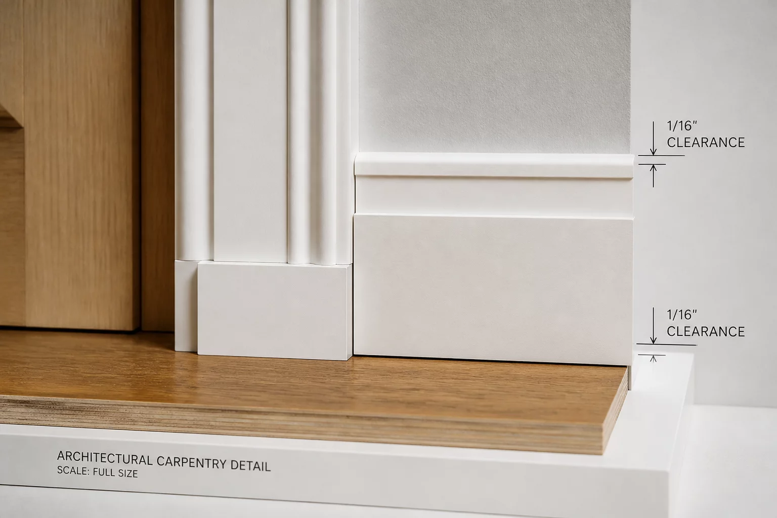
Clear guidelines for calculating perimeter linear footage and substrate expansion gaps along finished interior millwork assemblies.
 Specifications
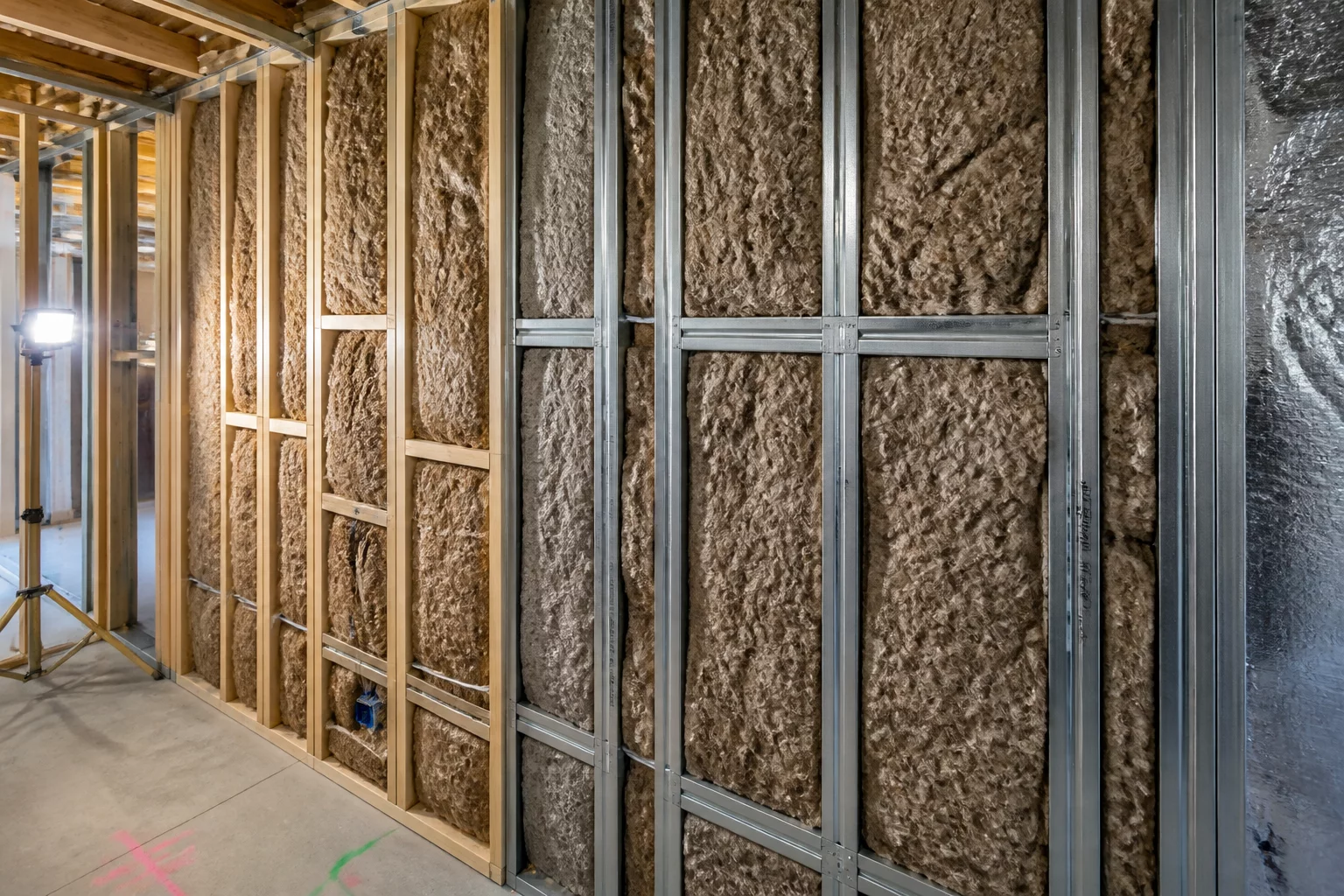
Differentiating stud cavity insulation, thermal barriers, and framing member quantities in compartmentalized repair matrices.
Discussion & Observations
No observations yet. Be the first to leave a comment.
Submit Methodology Observation