 Specifications
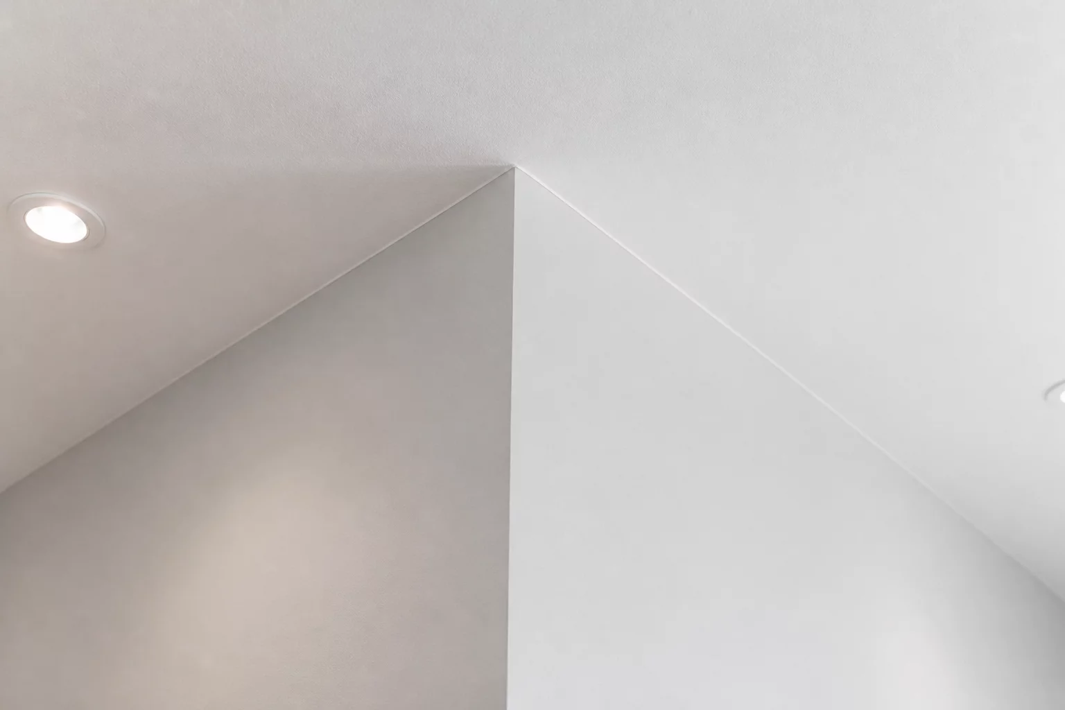
Continuous Drywall & Ceiling Plane Intersections
Defining ceiling boundary breaks where drywall runs continuously above partition framing across adjacent compartments.
Establishing clear vertical boundary definitions between structural framing decks, underlayment leveling substrates, and decorative wear surfaces.
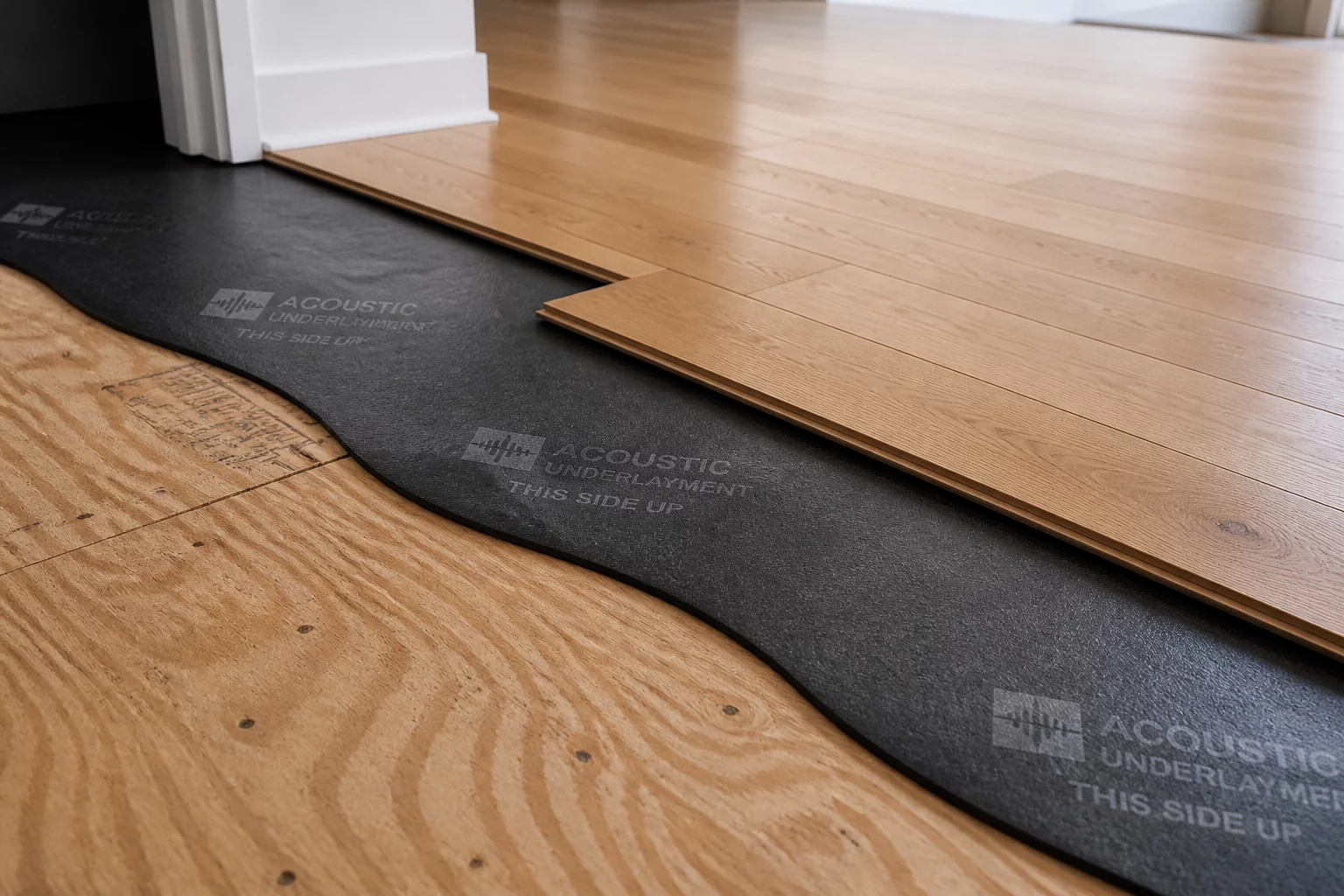
Scoping errors frequently emerge when estimators bundle the underlying structural subfloor deck, leveling mortar beds, and final architectural floor coverings into an aggregate square-footage calculation. In actual construction reality, each layer serves fundamentally distinct structural, moisture-mitigation, and acoustic roles, requiring segregated spatial assignments across different line-item codes.
The subfloor substrate functions as a horizontal structural diaphragm tied directly to floor joists and perimeter sill plates. Treating subfloor repairs within the same operational boundary as cosmetic plank replacement leads to major discrepancies during tear-out evaluations, particularly when localized water saturation impacts the subfloor framing while leaving surface finishes salvageable elsewhere.
Framing carpenters, tile masons, and hardwood installers rarely occupy the job site concurrently. When estimators record subfloor patching directly onto finished room surface takeoffs, project auditors cannot accurately decouple demolition labor from finish installation schedules. Establishing a clean plane-break rule ensures that every remediation step carries independent labor rates, square-foot wastage allowances, and surface clearance parameters.
“Treating the subfloor and the finished flooring as a single composite unit obscures fastener inspection requirements and inflates labor waste multipliers.”
Perimeter expansion gaps also emphasize the necessity of this vertical separation. Modern floating vinyl and hardwood systems require 1/4" to 3/8" perimeter expansion along baseplates, while subfloor sheathing demands an 1/8" expansion gap at structural panel edges. Conflating these zones distorts perimeter linear footage metrics and introduces perimeter trim interference risks.
Subfloor removal exposes joist framing, wiring, and plumbing cavities, requiring structural carpenters and safety inspections. Combining it with finish surface removal obscures trade scope, risk profiles, and localized repair perimeter boundaries.
Acoustic underlayment functions as an intermediate decoupling membrane. In the RepairZone Matrix protocol, it is mapped to the substrate preparation tier rather than the architectural wear layer.
The primary reference plane is the top face of the structural joist/decking assembly. Any leveling beds, self-leveling cements, or isolation mats occupy separate sub-layer profiles in the documentation sketch.
At the bond line between underlayment and finish material; each layer is a separate surface-role row sharing the same zone boundary.
By the damaged panel footprint inside the zone, with seams aligned to joist layout so replacement quantities stay defensible.
To the substrate row; finish rows reference the same reading by note so removal scope is justified at the correct layer.
Specifications
Defining ceiling boundary breaks where drywall runs continuously above partition framing across adjacent compartments.
 Specifications
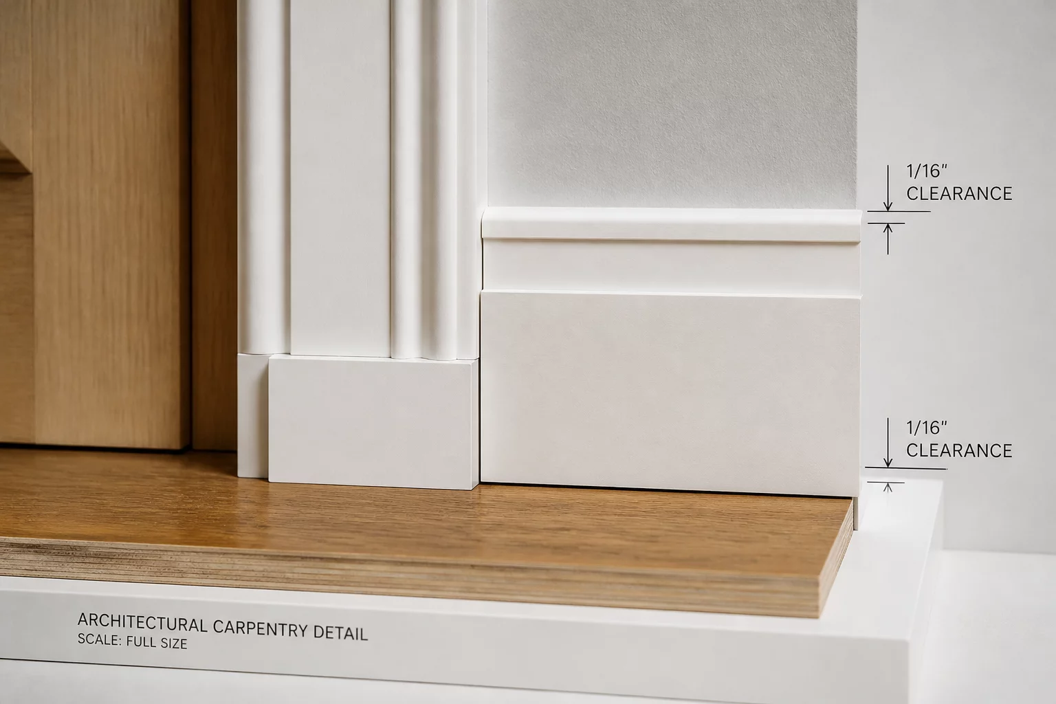
Clarifying vertical expansion tolerances and trade handoffs between finish base molding and substrate perimeters.
 Specifications
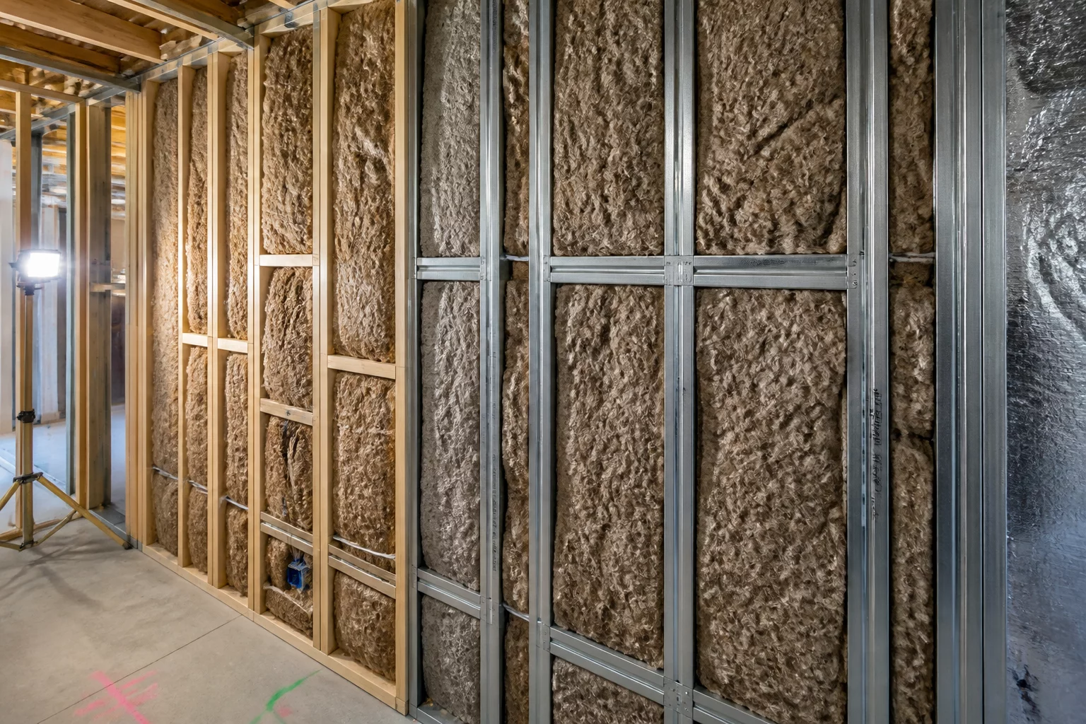
Boundary guidelines for separating stud bay insulation, vapor barriers, and interior wallboard enclosures.
Discussion & Observations
No observations yet. Be the first to leave a comment.
Submit Methodology Observation